Failure of Stamped T Slot Nuts in Precision Assembly
Stamping presses – high throughput stamping of sheet steel into T-shaped cross section. The technique is cheap for volume hardware, but three lingering faults preclude precision application. The burr formation along the shear edge inhibits flat seating inside the slot channel. The nut rides on a jagged contact line rather than a machined flat and tilts under the first off-axis bolt load. Second, as the progressive die wears during a production lot, the base thickness will vary, causing preload variation amongst nuts with ostensibly the same part number. Third, the thread alignment wanders over tens of thousands of die cycles, the tap following the stamping datum rather than another concentricity reference, thus the internal thread and the base lobe lose connection as the die degrades.
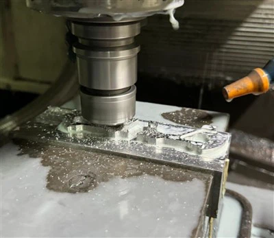
On a CNC worktable or robotic framework with sub-millimeter positioning to establish cycle accuracy the lateral play introduced by a stamped T slot nut with 0.15 mm base variation is amplified under vibration. Key-CNC removes these variables by cutting each nut from solid stock. The thread is single point cut concentric to the base within 0.03mm and the contact surfaces are polished to Ra 0.8μm or better. The result: Nut seats are flush, locking predictable, stays concentric-every piece, every batch.

Slot Fit vs Thread Fit – Two Precision Surfaces That Must Work Together
Two mechanical functions at once with CNC machined T slot nuts. The base lobe prevents the nut from moving laterally or rotating in the extrusion channel. The internal thread secures the bolt or stud that clamps the workpiece, transferring torque into axial preload. Failure of either surface defeats the fastener system. Stamped nuts frequently consider the slot fit a secondary consideration, with base width and depth decided by die geometry with generous clearance. Key-CNC machines surface to relationship tolerances that make the two functions support each other and not compete.
|
Critical Dimension |
Key-CNC Machined Tolerance |
Typical Stamped Tolerance |
Functional Impact of Drift |
|
Base width (slot engagement) |
±0.03 mm |
±0.12 mm |
Lateral rocking under off-axis bolt load |
|
Base-to-thread concentricity |
0.03 mm TIR |
Uncontrolled |
Bolt bending moment; premature thread wear |
|
Thread pitch diameter (6H/2B) |
±0.02 mm |
±0.08 mm (tap-only) |
Inconsistent clamp force across same-torque bolts |
|
Top surface flatness |
Ra 0.8 μm |
Shear edge + burr |
Nut tilts instead of slides; gouges slot wall |
Thus, when the bolt is off-center loaded, the nut cannot tilt sideways, which keeps the base width within ± 0.03 mm of the slot channel. This condition leads to progressive gouging of the slot wall in aluminium extrusions with loose stamped nuts. Similarly, concentric thread-to-base design minimises the bending moment that tears internal threads in thin-wall nuts under high clamp load. Extended thread engagement Key-CNC machines 1.2x nominal diameter vs. the 0.8x typical of stamped hardware spreads load over more thread turns, increasing effective torque limit by about 40 percent.
Three Types of T Slot Nuts and Why They Matter
Key-CNC offers three major T slot nut configurations, each to solve a different assembly limitation. Pick the improper style for the application and you have installation friction, or worse, a nut that won't go into the assembled frame at all.
|
Nut Style |
Installation Method |
Best Application |
Key-CNC Machining Advantage |
|
Slide-in T slot nut |
Insert from extrusion end; slide along channel |
Pre-planned frame builds; heavy axial loads; structural corner joints |
Base edges CNC-finished for smooth glide without drag burrs; full-length base engagement for maximum shear transfer |
|
Drop-in T slot nut |
Drop vertically into slot from top opening |
Post-assembly modifications; retrofit access panels; sensor bracket additions |
Machined rotation flat on base lobe prevents accidental dropout before bolt engagement; installer works one-handed |
|
Spring-loaded T slot nut |
Steel ball spring seats nut in channel during positioning |
Vertical frames; overhead installations where nut drop is a safety hazard; frequent reconfiguration stations |
Spring pocket CNC-drilled concentric to thread axis; ball retention cycle-tested to 500 insertions without spring fatigue |

Most T slot nut providers carry one or two styles, the remainder being special order with long wait times. All three key-CNC machines are from the same batch of material under the same ISO 9001:2015 process controls thus thread class, surface finish and material traceability are equal independent of style. A 50-piece prototype lot of slide-in nuts and a 50-piece prototype of spring-loaded nuts get the identical first article inspection and dimensions documentation-no quality tier distinction between standard and unusual configurations.
Galvanic Corrosion and Material Decision Matrix
CNC machined T slot nuts material selected based on warehouse availability rather than working conditions might cause galvanic corrosion, weight imbalance, and strength deficiencies downstream. The most prevalent T slot application, aluminium extrusion framing, makes material choice a corrosion-first and strength-second question. A galvanic cell forms when a steel nut touches an aluminium channel. After months of use, moisture condensation between the steel base and aluminium wall promotes extrusion side pitting, weakening the slot channel. Key-CNC uses a simple extrusion-specific decision matrix.
|
Material |
Core Advantage |
Typical Extrusion Environment |
Surface Treatment |
|
Carbon steel (Q235, 45#) |
Cost-effective; highest clamp force capacity |
Industrial frames, CNC fixture plates (dry or oil-mist environments) |
Zinc plating, black oxide, nickel - per assembly corrosion class |
|
Stainless steel 304 (A2) |
Corrosion resistance without additional coating |
Food processing lines, cleanroom enclosures, outdoor signage hardware |
Passivation ASTM A967; no plating needed |
|
Stainless steel 316 (A4) |
Resistance to chloride exposure and marine spray |
Coastal installations, chemical pump frames, battery module racks |
Passivation; optional electropolish for ultra-clean compliance |
|
Aluminum 6061-T6 |
Same galvanic family as extrusion - eliminates bimetallic cell entirely |
All-aluminum structural frames, lightweight robotic arms, portable test rigs |
Anodizing in custom colors for visual coding; matches extrusion finish |
|
Brass C36000 |
Non-sparking; electrically conductive for grounding contact |
ESD-sensitive workstations, explosive-environment fixture assemblies |
Natural golden finish; no plating required; inherent conductivity |
Key-CNC 6061-T6 aluminium T slot nuts minimise galvanic corrosion and provide thread strength for M4–M10 clamp loads in standard aluminium profile systems. Our carbon steel nuts are zinc-plated to interrupt the galvanic circuit at the steel-to-aluminum contact interface for M12 and above applications or dynamic vibration conditions. Before installation, the assembly engineer checks each batch's material certificate for plating thickness and specification to ensure corrosion protection fits the service environment.

To Avoid Three Common Failure Modes; Assembly Protocol
Installation and geometry can preclude three T slot nut assembly field returns. Understanding failure signs before buying gear reduces retrofit expenses.
● Too much torque strips threads. Slot channel dimensions limit T slot nut wall thickness. Shears and lengthens internal thread with bolt torque above proof stress. Key-CNC machines increase thread engagement length to 1.2× nominal diameter, dispersing clamp force across more turns and increasing torque limit by 40% over stamped nuts. Shipments contain material and thread size torque advice sheets.
● Uneven loading deforms slot-wall. Bolt tightening permanently gouges the aluminium channel with the nut base's large edge, weakening subsequent nut installations. This is a typical production flaw. The Key-CNC base width tolerance of ±0.03 mm enables symmetric contact and homogeneous pressure distribution on the slot floor, preventing localised deformation.
● Inserting rotating-nut bolts. From above, thread drop-in and slide-in bolts with the nut orientated. The assembler must retain stamped nuts with free-rotating base corners with a second tool or fingertip pressure. Assembly lines with hundreds of nut placements every shift benefit from Key-CNC's small base lobe anti-rotation flat that engages the slot floor edge for one-handed bolt tightening.
Dimensional Capabilities and Ordering Flexibility
|
Parameter |
Capability |
|
Thread size range |
M3 – M16 metric; #4 – 5/8" inch; custom pitch available |
|
Base width (slot match) |
Per profile drawing; typical 6 mm – 20 mm |
|
Base-to-thread concentricity |
0.03 mm TIR |
|
Thread class |
6H/6g metric; 2B/2A inch; single-point CNC cut |
|
Surface roughness |
Ra 0.8 μm standard; Ra 0.4 μm on request |
|
Anti-rotation flat |
CNC-milled per slot geometry; prevents free-spin during bolt insertion |
|
Spring pocket (spring-loaded style) |
CNC-drilled concentric to thread axis; ball retention tested to 500 cycles |
|
Thread engagement length |
1.2× nominal diameter (standard); adjustable per application torque requirement |
|
ISO 9001:2015; material certificates, dimensional reports, and slot-fit verification per batch |
|
|
Prototype lead time |
5 – 7 working days from drawing approval |
|
Production lead time |
2 – 4 weeks |
|
MOQ |
No minimum order; 20-piece prototype lot receives full process controls and traceability |

Hot Tags: cnc machined t slot nuts, China cnc machined t slot nuts manufacturers, suppliers, factory