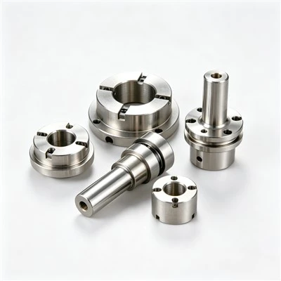
A bushing is more than a simple cylindrical component. It serves as a tribological interface between a shaft and housing, controlling motion through accurate dimensions, proper clearance, material compatibility, and surface finish. This is why CNC machined bushings require tighter control than standard turned parts.
- Even small dimensional deviations can affect the entire assembly:
- Incorrect bore clearance can reduce lubrication performance, increase friction, and accelerate wear.
- Poor interference fit may cause the bushing to rotate inside the housing, leading to bore damage.
- Loss of concentricity can create shaft misalignment, vibration, and premature component failure.
Our engineers review each bushing drawing with the complete assembly in mind, providing DFM feedback on critical features such as bore diameter, outer diameter, length, wall thickness, concentricity, and surface finish. This helps ensure the final part meets both dimensional requirements and real-world operating conditions.

Bushing and Sleeve Configurations We Machine
Key-CNC machines a full spectrum of bushing and sleeve geometries. Each configuration addresses a specific functional requirement in the assembly:
| Configuration | Description | Typical Use Case |
|---|---|---|
| Plain sleeve bushings | Straight cylindrical bore and OD, uniform wall | Pivot points, guide pins, shaft supports, linear motion guides |
| Flanged bushings | Integral flange at one end for axial location | Thrust load management, axial positioning without separate washers |
| Thrust washers | Flat disc with precision bore and parallel faces | Axial load distribution between rotating faces, gear thrust surfaces |
| Split bushings | Axially split for clamp-on installation | Maintenance-accessible assemblies, field-replaceable wear inserts |
| Threaded bushings | Internal or external threads machined to spec | Adjustable clearance mechanisms, grease fitting interfaces, precision thread adjustments |
| Grooved bushings | Internal or external lubrication grooves (axial, circumferential, or helical) | Oil distribution, grease retention in high-load and intermittent-service applications |
| Stepped bushings | Two or more diameters with transition shoulder | Transition fittings, spacer-sleeve hybrids, multi-diameter shaft interfaces |
| Custom profiles | Non-standard features per drawing (cross-holes, flats, keyways) | Application-specific requirements combining multiple functions |
Every configuration is produced to your drawing specifications. We accept STEP, IGES, DWG, and PDF files and combine CNC turning for cylindrical features with CNC milling for flats, slots, and cross-holes - all in a single setup when geometry allows, eliminating datum shift errors between operations.

Critical Dimensions and Inspection Methods for Bushings
Bushing quality control goes beyond verifying that the part matches the drawing. The inspection must confirm that the bushing will function correctly in its assembly - which means measuring relationships between features, not just individual dimensions.
| Critical Dimension | Inspection Method | Why It Matters |
|---|---|---|
| Bore ID (inner diameter) | Air gauge, precision bore micrometer | Controls running clearance with shaft - the single most critical dimension |
| Outer diameter | Digital micrometer, CMM probing | Determines interference fit in housing; loose fit causes bushing rotation |
| Concentricity (ID to OD) | CMM, V-block + dial indicator | Prevents uneven wall thickness and eccentric rotation under load |
| Wall thickness | Ball micrometer, ultrasonic measurement | Thin walls risk deformation under press-fit and operating loads |
| Surface roughness (bore) | Profilometer (Ra measurement) | Affects lubrication film retention and break-in behavior |
| Length / face squareness | Height gauge, optical comparator | Ensures proper axial positioning and flush seating against housing shoulder |
| Hardness (post-heat-treat) | Rockwell hardness tester | Confirms wear resistance meets specification after hardening |
Our process includes 100% first-article inspection and batch sampling per ISO 9001:2015 requirements. For critical bushings in robotics or medical devices, we provide full dimensional inspection reports with material certificates traceable from raw stock to finished part.

How to Specify Custom Bushings for Your Project
To receive an accurate quote and DFM feedback within 24 hours, include these details when you request a quote:
- Drawing files - STEP or IGES for 3D, DWG or PDF for 2D. Include tolerance callouts on critical features (bore ID, OD, length, concentricity).
- Material specification - Alloy grade if known (e.g., C93200 bronze, 4140 steel). If unsure, describe the operating environment and load conditions and we will recommend.
- Shaft material and hardness - This determines bushing material compatibility, required surface finish, and whether a dissimilar-metal pair will resist galling.
- Operating conditions - Speed (RPM or linear velocity), load (radial and axial), temperature range, lubrication method (grease, oil, dry), and expected service life in hours or cycles.
- Quantity and timeline - Prototype (1–10), pilot run (10–100), or production volume (100+). No MOQ - we support projects at every stage from rapid prototyping to serial production.
- Surface treatment requirements - Specify if honing, plating, or coating is needed, or let us recommend based on your application environment.
Frequently Asked Questions
What tolerance can you achieve on bushing bore diameters?
+
-
Our standard machining process delivers reliable dimensional accuracy for most bushing applications. For precision requirements, we use advanced CNC machining and inspection methods to achieve tighter bore control and ensure proper fit, alignment, and performance.
What materials can you machine for custom bushings?
+
-
We machine a wide range of bushing materials, including bronze, brass, stainless steel, aluminum, and engineering plastics such as POM, PEEK, and nylon. Material selection depends on factors such as load conditions, wear resistance, operating environment, and application requirements.
What is the difference between a bushing and a sleeve?
+
-
In precision machining, the terms are often used interchangeably. A bushing is typically designed to support moving components and reduce friction, while a sleeve may also function as a spacer, alignment guide, or protective liner. Both require accurate bore and outer diameter machining to ensure proper assembly performance.
Do you provide heat treatment for hardened steel bushings?
+
-
Yes. We support heat-treated steel bushings through qualified processing partners, including options such as hardening and surface strengthening treatments. These processes help improve wear resistance and service life for demanding applications.
What is the typical lead time for custom bushings?
+
-
Lead time depends on material, design complexity, quantity, and finishing requirements. Prototype and production schedules are optimized to meet project needs, with expedited options available for urgent requirements. Contact us with your drawings and specifications for a detailed quotation.
Hot Tags: precision cnc machined bushings and sleeves parts, China precision cnc machined bushings and sleeves parts manufacturers, suppliers, factory, CNC Lathe Milling Machining Parts Service, CNC Machinable Materials and Processing Flow, CNC Machine Setups and Parts Orientation, CNC Machining Services Apply To Parts Made Of Various Metals Materials, Prototype Production CNC Machining with DFM Support, The Machining Process and Differences Of 3 axis 4 axis and 5 axis CNC