Reading the Callout: What M3 x 12 + 6 Actually Specifies
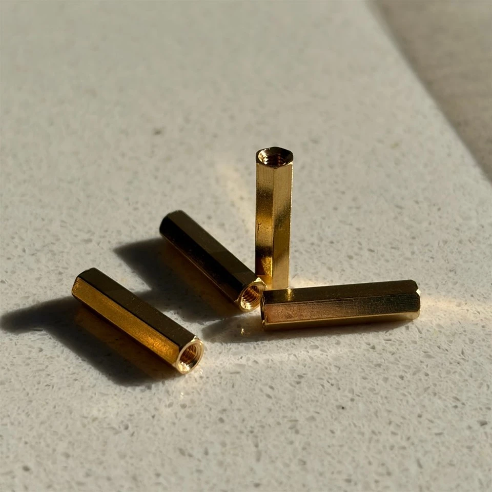
The part number looks cryptic until you split it into three fields. M3 is the thread size on both the stud and the female end. 12 is the body length - the distance between the two shoulders that the boards actually bear on, which is the dimension that sets your stack height. + 6 means each male end carries 6 mm of usable thread. Those numbers are read differently than a bolt's, because the part's job is to hold a gap while its threads merely connect: tightening the screw should close the joint onto the shoulders, not wind the boards together through the threads. On a hex body, the across-flats size is chosen so the column can be held with a standard wrench while the screw is driven from the other side - the detail that makes repeated rework practical.

Where a Brass Hex Standoff Outperforms Aluminum and Nylon
Aluminum hex standoffs are lighter and cheaper, and for a purely mechanical stack they are a sensible default. Brass takes the position when the joint has an electrical role or a long service life with rework. Brass conducts, so a column screwed into a grounded chassis provides a low-resistance path from the board's mounting pad to earth - useful for grounding stitches, EMI gasket compression and shielding cans. Brass threads also survive reassembly; an anodized aluminum thread wears at the crests after several service cycles, exposing bare metal that then oxidizes under the screw. Compared with nylon, brass does not creep under preload, holds its thread geometry through temperature swings and can be machined to tighter thread classes. The trade-offs are weight and material cost, which at PCB scale are usually trivial.
A Worked Stack-Up: Two Boards, One Chassis, One Ground Path
Consider a common build: a 2 mm aluminum chassis, a 1.6 mm main board mounted above it, and a 1 mm sensor board above that. Choosing an M3 x 12 male-female standoff for the upper tier leaves the main board screwed onto the male studs below, with washers bearing on the chassis; the lower tier uses the same thread, so one driver and one screw type serve the whole assembly. Because every column is machined from the same C360 bar stock, the four mounting points share identical stack height, and the ground path runs continuously from the main board's mounting pads through the columns into the chassis. When the sensor board needs to come off for firmware access or probing, the screws back out, the columns stay seated in the chassis, and the geometry is untouched. That serviceability is the real argument for threads on both ends rather than press-fit pins.
Threads and Lengths: How Tight the Numbers Run
Threads are cut in-house in both systems: metric to ISO 6g on male studs and 6H in female ends, unified to ASME 2A/2B, and mixed metric-to-imperial combinations for retrofits where an imported module meets a locally made chassis. On a brass hex standoff, length is the dimension buyers worry about most, and with reason - 0.1 mm of error across four columns tilts the board and stresses its solder joints. Machined faces are held within plus or minus 0.01 mm, and the shop's working envelope spans part sizes from 2 mm to 1000 mm, so the same supplier handles M2 column mounts and large panel-spacing hardware. Female thread depth is sized so the mating screw bottoms out only after the joint is closed - forgetting that is what produces cracked PCB corners.

FAQ
Q: Can these columns really carry current between boards?
A: Yes - the brass body is conductive end to end, and joint resistance stays low when the mating surfaces are clean and the screw is properly seated. For safety-critical grounding paths, specify bare brass and verify contact resistance after assembly rather than relying on the screw thread alone.
Q: Do brass standoffs help with EMI?
A: They contribute: metallic columns shorten the gap between a shielding can and the chassis, giving interference a shorter return path. A complete shielding design still depends on gaskets and enclosure geometry.
Q: What is the length tolerance on a custom brass hex standoff?
A: Machined faces and shoulders are held to within plus or minus 0.01 mm; thread pitch and class follow the drawing.
Q: Male-female or male-male - which suits a grounded stack better?
A: Male-female is the default: the female end threads onto a stud in the chassis and grounds through it, while male-male standoffs suit stacking two boards where both ends screw into tapped pads.
Q: Can threads be supplied in 4-40 UNC or M2.5?
A: Yes - both unified and metric sizes are cut in-house, including combinations where an imported module meets a locally made chassis.
Q: Do brass standoff threads need locking compound?
A: Usually not for indoor electronics. A nylon patch can be pre-applied for assemblies that see vibration or thermal cycling, and chamfered lead-ins can be added to guide alignment during assembly.
Hot Tags: brass hex standoff, China brass hex standoff manufacturers, suppliers, factory